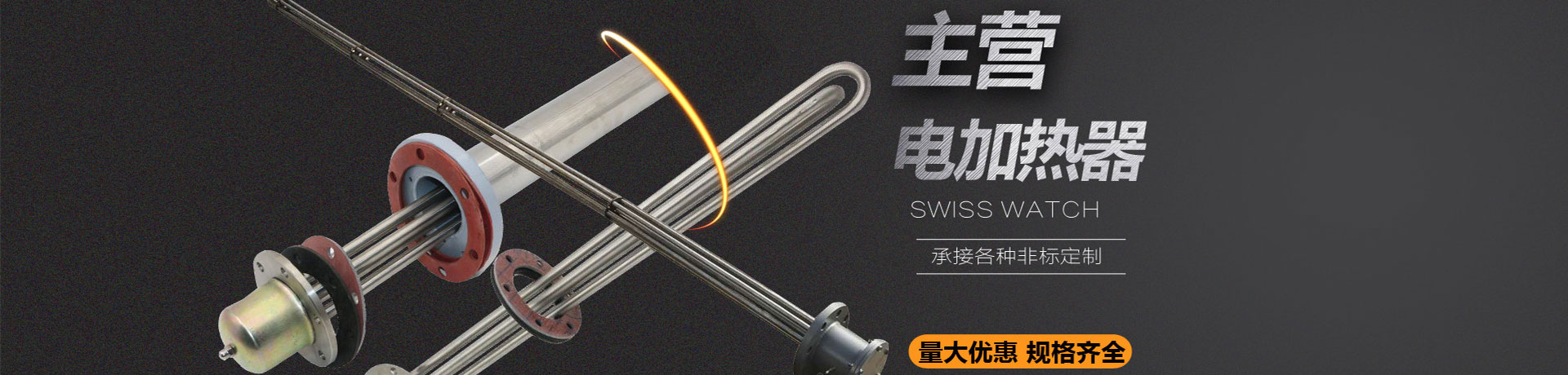
Before determining the model and structure of the HZQ-650 finned tube heat exchanger, the medium name, flow rates on both sides, inlet and outlet temperatures, and allowable pressure drop must be provided to the designer. These parameters are used for thermal calculations and resistance calculations to determine the number of finned tube rows, fin spacing, number of tube passes, and heat exchange area. If the medium is dust-laden flue gas, the dust concentration and particle size distribution must also be specified to assess the fouling tendency and adjust the fin spacing.
The fin spacing of this heat exchanger is designed for gaseous media. Although it is easier to purge with compressed air than a plate-frame heat exchanger, the flow channels on the fin side are narrow and have dead zones. If used for fouling-prone liquid media, the fouling layer will quickly fill the fin gaps, causing increased air resistance and reduced heat exchange efficiency, and the cleaning frequency will increase significantly. Therefore, the applicable media on the fin side are gases such as dust-laden flue gas and air, or clean liquids with low fouling tendency.
The HZQ-650 is suitable for gas-liquid and gas-gas heat exchange applications such as dust-laden flue gas waste heat recovery, air heating, or cooling. The finned tube structure enhances gas turbulence on the fin side, and the heat transfer coefficient is improved compared with bare tubes; the tube side can carry liquid or steam. Compared with plate-frame heat exchangers, this model has larger fin spacing, facilitating online purging and maintenance. During design, the fin spacing can be adjusted according to the dust content of the flue gas to balance heat transfer performance and fouling risk.
During equipment installation, space should be reserved for purging on the fin side, and temperature and pressure measurement points should be set at the inlet and outlet to facilitate monitoring of pressure drop changes. The baseline pressure drop should be recorded in the initial operation period, and purging should be arranged when the pressure drop rises significantly. Vent and drain ports should be provided on the tube side according to conventional heat exchanger requirements. For dust-laden flue gas conditions, it is recommended to install a pre-dust removal device upstream of the fin side to extend the cleaning cycle.