
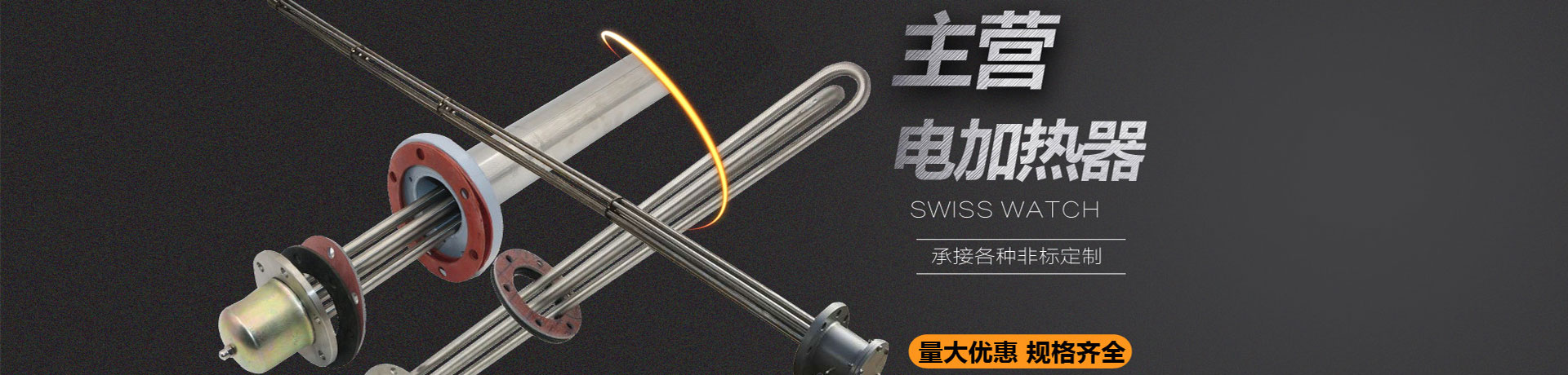
In engineering applications of explosion-proof electric heaters, the 100mm range of the heating tube near the flange face is often regarded by technicians as a critical area. Why does this section require special attention? This is directly related to the explosion-proof structure, temperature distribution, and sealing reliability.
Q: Why should this 100mm range be considered separately?
A: The flange face is the boundary between the explosion-proof wiring cavity and the medium heating cavity. The heating tube passes from the flange into the medium cavity, and within the first 100mm of its root, it is simultaneously affected by heat conduction from the medium and heat dissipation from the flange, resulting in a large temperature gradient. If the heat dissipation design is improper, it may cause local overheating and affect the maintenance of the explosion-proof surface temperature class (such as T4-T6). Therefore, this section needs thermal verification based on the medium temperature, flange material, and heat dissipation conditions.
Q: How can the temperature uniformity of this section be controlled?
A: The internal control system automatically adjusts the output power based on the outlet temperature sensor signal, which can indirectly stabilize the overall heat output of the heating tube. However, the 100mm range near the flange relies more on structural design: appropriately adding heat dissipation fins or using a thermally conductive sleeve helps reduce the root temperature. At the same time, the outlet air temperature and flow rate can be controlled by variable frequency speed regulation to avoid local overheating caused by flow fluctuations.
Q: What parameters need to be provided during selection?
A: It is necessary to specify the medium name, working pressure, inlet and outlet temperatures, flow range, and explosion-proof area classification (gas or dust). For the 100mm section, the flange specifications, material, and allowable upper limit of surface temperature should also be stated to calculate the heat flux density.
Q: What should be noted during maintenance?
A: Regularly check this section for carbon buildup, scaling, or decreased insulation resistance. If a temperature controller is installed in the explosion-proof wiring cavity, verify the deviation between its actuation value and the actual root temperature. Avoid damaging the explosion-proof surface during disassembly.