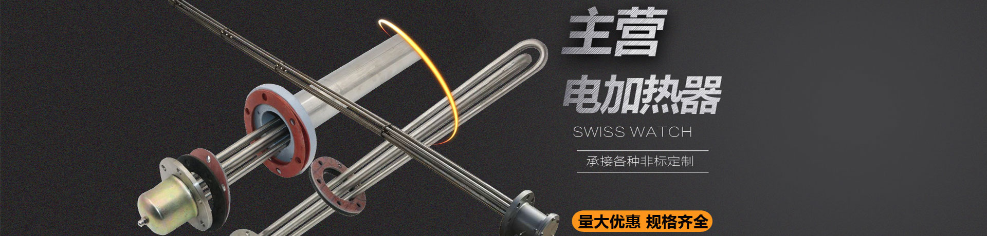
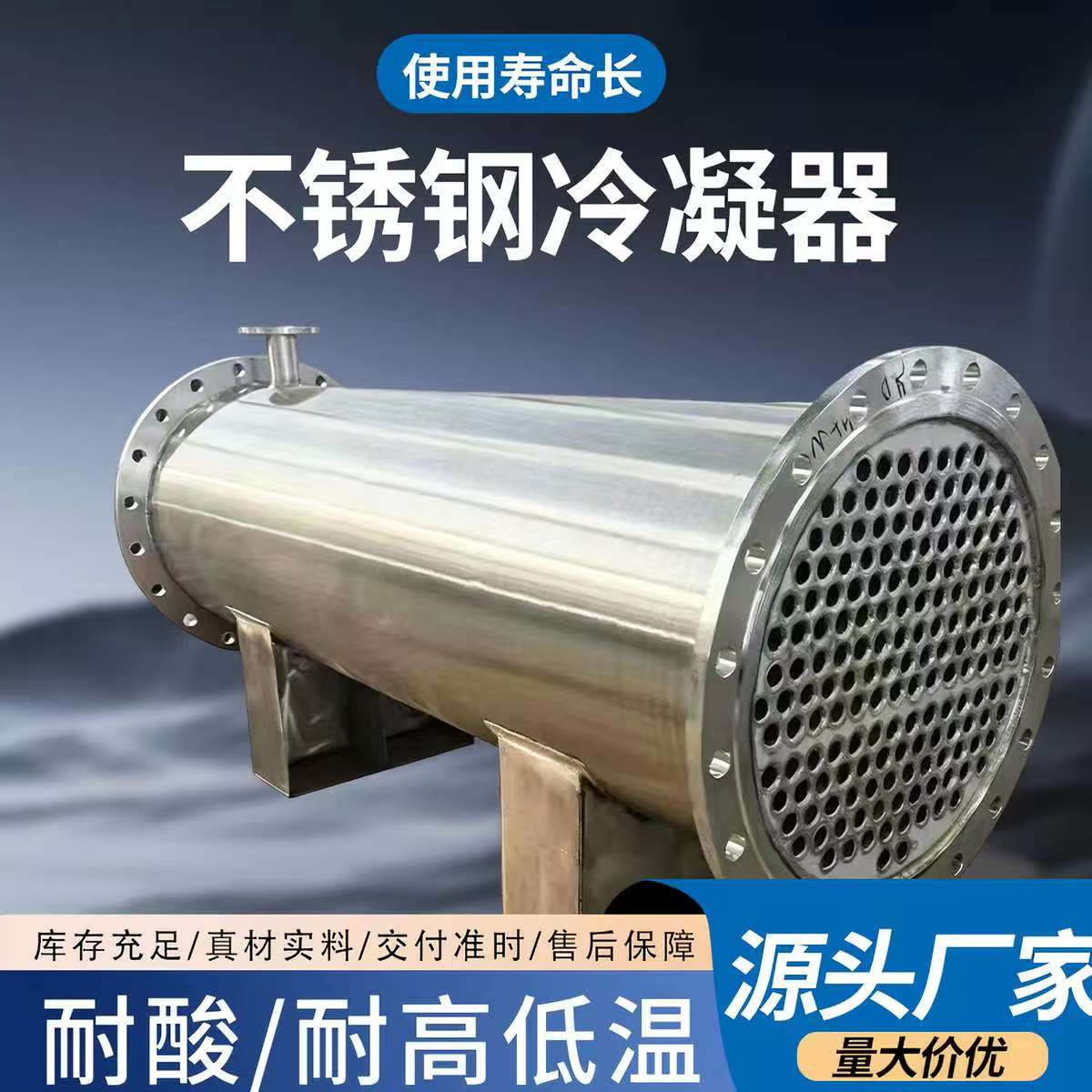
During design and selection, a common problem is encountered: when dust-laden flue gas is passed through the fin side, the heat exchange efficiency drops sharply in less than three months of operation. Upon inspection, ash bridging between fins is found, making cleaning difficult. Should finned tube heat exchangers continue to be selected?
Compared with plate-frame heat exchangers, the KFS-600 finned tube heat exchanger has a larger fin spacing. This design facilitates online or offline blowdown with compressed air and can reduce the frequency of shutdown cleaning caused by ash deposition. However, it should be noted that the fin side is not suitable for liquid media prone to scaling; otherwise, the cleaning frequency will increase significantly. During selection, priority should be given to confirming whether the medium side contains scaling-prone components.
For dust-laden flue gas applications, the flow velocity on the fin side is recommended to be controlled at 8–12 m/s. If the flow velocity is too low, dust tends to deposit on the fin surface; if too high, fin wear will be aggravated. Designers should comprehensively determine the tube bank arrangement based on the dust content of the flue gas, particle size distribution, and allowable pressure drop, and should not select solely based on a single indicator such as heat exchange area.
The tube bundle material of the KFS-600 finned tube heat exchanger can be carbon steel, stainless steel, or corrosion-resistant alloy, and the fin types include wound fins, embedded fins, etc. The design pressure, design temperature, and connection specifications can be customized according to project requirements and should be clearly marked on the nameplate.
This type of heat exchanger is suitable for gas-liquid and gas-gas heat exchange occasions such as waste heat recovery from dust-laden flue gas, air heating, or cooling, but it is not recommended for liquid media prone to scaling on the fin side. During selection, complete medium parameters, flow rate, inlet and outlet temperatures, and allowable pressure drop must be provided for thermal and hydraulic calculations.